Tuesday, December 9, 2014

Day 24 Motional EMF

In this lab day, we focused on combining all of the basic laws that we knew about for magnetism, and building one general rule for all of these scenarios, called Maxwell's Equation. We also begin talking about inductance and adding it to the list of things we can have in a circuit.

Real life usages of inductors
Prof Mason brought in chip commonly found in many electrical appliances, and showed us that in this chip, all three of what can be in a circuit, a resistor, a capacitor and a new one, an inductor are all being used in this chip. It is to note that the inductor is the shiny copper like wires that are sticking out from the wires


Electromagnetic Induction
We are told to go on an ActivPhysics website, and were to answer question based on electromagnetic induction. All the answers to the questions are below at the bottom pages


 The RL Circuit Simulation
The following questions are answering questions involving a resistor, an inductor and a battery
Question 1

Questions 2-8
 Due to this experiment, we got to understand that just like a capacitor, an inductor is time-dependent, and that in this case, tau (time constant) is equal to L/R, vs how the tau in a capacitor is equal to RC

Introduction to Inductance
In this lab, we are using the oscilloscope in order to find out the behavior of an inductance when a function generator shoots its frequency through it
The oscilloscope reading

The entire circuit connections

Connections to the inductor

Connections to the resistor

Calculations of the experimental inductance and the wire turns

Example problem involving 
The final thing we did for the day was now combining all three pieces of the pie, a resistor, a capacitor, and an inductor into one circuit, an LRC circuit, and solving questions based off it.
Note, in this question, the 750 ohm resistor doesn't affect the entire loop, since it is connected parallel to the capacitor, the inductor and the 120 ohm resistor.

Day 25 RL Circuits

Today, we go over RL (Resistance and Inductance) Circuits, to better understand exactly how induction works.

We took to an understanding exactly the importance of max peak and root-mean-square of both voltage and current (in AC, its the rms that matters, not the max peak). We find that the rms is 0.707, which is known as both the cos and sin of pi/4 or 45 degrees


The next following pictures are of the lab "RMS and AC Current and Voltage" where we find the rms vallues and max values given certain information

Part 1:
The first three pictures are of part one, in which we used the resistor of about 100 ohms, and measured multiple things from it.

Graph of the resistance in AC
Voltage vs current graph for resistance

Answering the questions
It is to note that in a resistance, the phase angle is in fact zero, that the resistance and the voltage are in phase with each other, which is shown by the voltage vs current graph, meaning the V=IR equation from Ohm's Law still applies in AC

Part 2
In part 2, we used a capacitor with indicated capacitance in order to find the relationship between voltage and current in a capacitor in AC

Capacitor graph (voltage vs current on the bottom)

Answering the questions of capacitance
Part two's experiment shows that the voltage and current in a capacitor in AC is not in phase with each other, and that the voltage is in fact ahead of the current by about 90 degrees

Part 3:
Part 3 focused on two parts, an inductor without an iron core and inductor with an iron core, to see if any difference arise as a result from it.
Solving the questions for inductors


The graph of the inductor with the iron core

Solving the questions of the inductor with the iron core

In part 3, I figured that since the experimental error of the inductor without the iron core showed to be over 10% (around 7x more) that I don't really need to see the graph, since the graph shows a lot of errors. However, with the iron core, we show that in the inductor, just like the capacitor, the voltage and the current are not in phase with each other, in fact in the inductor, the current leads the voltage (voltage lags the current) by 90 degrees, the complete opposite of the capacitor


Day 26 AC Circuits

In our very last lab together, we go over the importance of AC circuits and the LRC (induction, resistance, and capacitor) circuit within an AC (Alternating Current) system. It is to note that we did not cover through a lot of labs in this section, due to time constrictions, and therefore the amount of pictures shown are limited

We went through the class first learning about phase angles, and how the current and the voltage, while in an AC circuit, should not be in phase which each other. The phase angle is when the peak voltages are either ahead or lagging the current.
It is to note that in for the following circuits, the following angles are true
Pure resistance: 0 degree angle
Pure capacitor: 90 degree angle
Pure inductor: -90 degree angle
A RL circuit: phase angle can be found between 0 and  90 degree
A RC circuit: phase angle can be found between -90 and  0 degree
A LRC circuit: Greater than 0 if XL > XC, less than 0 if XC > XL, and 0 when in resonance
An example problem dealing with RLC circuit

This example problem is probably the first time we have combined a resistor, a capacitor and an inductor into one, finding the resonance frequency, the current, and the power dissipated


Third portion of the lab
We had a lab that demonstrated series RC circuits (unfortunately, my phone has deleted most of this lab, so all I have is the third portion), in which we were to set up an RC circuit in an AC system to see if anything changed between DC and AC
The graph shown on this picture was an error caused by have the voltmeters collecting the voltages at both the resistors and the current at the same time, when it was proven that it would not work, creating what looks like a system that should be in phase when it is not in actuality.


Demonstration of transformers
One of Prof Mason's last demonstration was of transformers, which is essentially two largely coiled wires connected to a U-shaped magnet. We find out that these transformers are actually used everyday in power lines
By knowing that the power within the two inductors are the same, we can then find the change in currents, by looking at the ratio of the amount of turns in the wiring, and the initial current.

Day 21 Motors and Magnetic Field

Today we go over more about magnetic fields, this time focusing more about magnetic motors

Morning exercisee
The first portion of the lab was a recap on how magnetic field and magnetic force works. We were given an area with a magnetic field pointing a certain direction, and was asked to find where the force was at a certain point.
We find that since the magnetic field is perpendicular to its force, that only the top and bottom portions of the area would exert any force at all
 Alongside the morning exercise, we learned that when the magnetic force is parallel to an object, that it exerts no torque, meaning that the center at which the object rotates does
Relating force to torque


We then took what information we know about magnetic force and Torque and applied them into an equation that could now find torque, using the magnetic field, the area, and the current of the system


Explanation of a magnetic motor
 The next picture showed an interesting lab, in which Prof Mason shows to us that it is possible to rotate the magnet in the middle using nothing but magnetism. By constantly having the switch move between positive and negative at a specific point (once the magnet was given an initial push), we showed that it was possible to get the magnetic to rotate both clockwise and counterclockwise.
It is to note however, that the way this motor was created was fairly inefficient as it took near perfect precise timing in order to get the magnetic to spin at a relatively fast rate.


More explanation of a n electric motor
 Prof Mason goes on to explain that when the electric motor operates, when it reaches to a certain "grey" area, it actually temporarily turns off, before it goes back, which was seen during the electric motor demonstration


A Saint Louis Motor
 Our next lab required working alongside the Saint Louis Motor, a motor that has two magnets on the opposite side of each other and some metal in the middle of it. It spins once we added current to the system. We were then asked to answer a few questions (on the next picture below) on the Saint Louis motor, and if any changes occur when we switch it from its initial set up.
It is to note our specific motor took some time to spin, as it requires very little friction to operate smoothly
Our answers to the Saint Louis Motor Lab

Creating our electric motor
Our next task, once we took an understanding of how a motor works was to create a simple electric motor ourselves, using some current, powerful magnets, and some coiled wire (making sure we sand 180 degrees to remove the copper)
It is to note that the setup that we have in our picture was not our original setup, but the initial setup was much more complicated and took more time than needed for it to work .
A video of the simple motor operating 


Setup of the Magnetic Field near a current-carrying wire
 In this next lab, The Magnetic field near a current carrying wire, we studied what would occur to a bunch of compass needles if it was placed circular to a rod that is carrying current, and thereby a magnetic field.
Our initial prediction was that all of the metals would all point at the metal rod, for that is the one providing the current
Magnetic Field near a current-carrying wire experimentation
 We find out that the compass needles are not pointing to the current-carrying rod, but rather it follows the magnetic field that the current is producing, which turns out to be counterclockwise
Our theory and actuality in this lab

Setup of the experimentation
 The last lab talks about whether or not a magnetic field can superimpose each other, or does the magnetic fields change due to different wiring arrangement. We were asked to predict the strength of the magnetic field at three points, one initially at the beginning, once it goes down the first hill, and after it goes through a loop

Although not all were being shown, we do find out that the magnetic field does in fact change throughout the system. I believe it was the loop itself that showed to have no magnetic field, due to the fact that the magnetic fields of both the top and the bottom are cancelling each other out, creating no magnetic field as a result.


We ended class by understanding just how important the relationship between electricity and magnetism is (and how electromagnetic force came to be) by looking at their equations, and from that coming up with a ratio between the two forces

Monday, December 8, 2014

Day 20 Magnetic Field


Today we began focusing on a new topic, the second portion of the electromagnetic field, magnetism.
A magnet pin controlling a compass
We first started class by Prof Mason demonstrating just what a magnetic field is by having a magnetized pin around the compass and moving the magnetic pin. We notice that the north side is following the magnetic pin


A discovery of how magnets work
We found out that magnets contain a north pole and a south pole, with the opposite attracting each other and the same repelling each other (just like how a proton and electron works)
We also see that if you cut a magnet in half, the ends of those sides become south and north respectively, meaning that it is impossible to have a single north/south side, otherwise known as a magnetic mono-pole

A Maxwell Equation, the integral of B (magnetic field) dA = 0 shows that there is no such thing as a magnetic monopole


Magnetic Flux
We then go on to study about magnetic flux and the similarities between a magnetic flux and a electric flux


Experimentation on exertion of electric charge
We then go over to see whether or not we can exert force on electrical charges that are moving by using a magnet, and the electron beam of an oscilloscope. 

More on the experimentation

We find out that once we move the magnet closer to the oscilloscope electron beam, the beam moves over to the left, showing us that the magnetic moves perpendicular to the beam, and therefore the magnetic force is both perpendicular to the direction of the magnetic flux and the moving charge


Equation proving what we saw
The right-hand rule

We then learned about the right-hand rule, and how important it is to understand how it works so that we can get an idea of where the Force and the Magnetic Field's direction is going


Back-stepping

Learning about the right-hand rule, we can go back to what we saw from the electron beam, and figure out where the force is pointing, which in this case, the force is pointing into the board


The next following picture are class examples in which we focused on learning and understanding more about the right hand rule

Example 1
Example 2 


Deriving radius in magnetism


By using what we know about magnetic force, within a circular region, we are able to then derive an equation for the radius of said region


The next few photos cover over the idea of rotation, primarily omega (angular velocity) and an example problem with it 


Electric field on a current carrying wire

We then studied the magnetic force of a current carrying wire understand the nature of a non-magnetic wire placed in a permanent magne


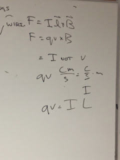
Deriving another formula for magnetic field
We learned from the experimentation that there is indeed a magnetic force of the wire when the wire starts carrying current, and both the length and the current are perpendicular to the magnetic field, which gives us a second equation for magnetic force = ILxB, where I is the current, L is the length, and B is the magnetic field


Add caption

To get more of a grasp of how the magnetic field and force works, we were given a system where the magnetic field's direction is known, and asked where the magnetic force is point at each instance
We learned that the magnetic force only point when the magnetic field is parallel to the points shown, therefore only B and D are shown to have a force, pointing inside and outside respectively.